After my progress on PCG last week, I thought I would try and mess about a bit with PCGEx, the free plugin you can get here – https://www.fab.com/listings/3f0bea1c-7406-4441-951b-8b2ca155f624
There are a couple of sets of documentation for it – a newer version currently work in progress.
However, I was concerned that there was quite a wide gap between my understanding of some of the mathematical concepts introduced in it and the need to have this to even begin to get to a basic view of what I was trying to do.
Starter Graph
Therefore, I’ve just tried to build up with something VERY basic.

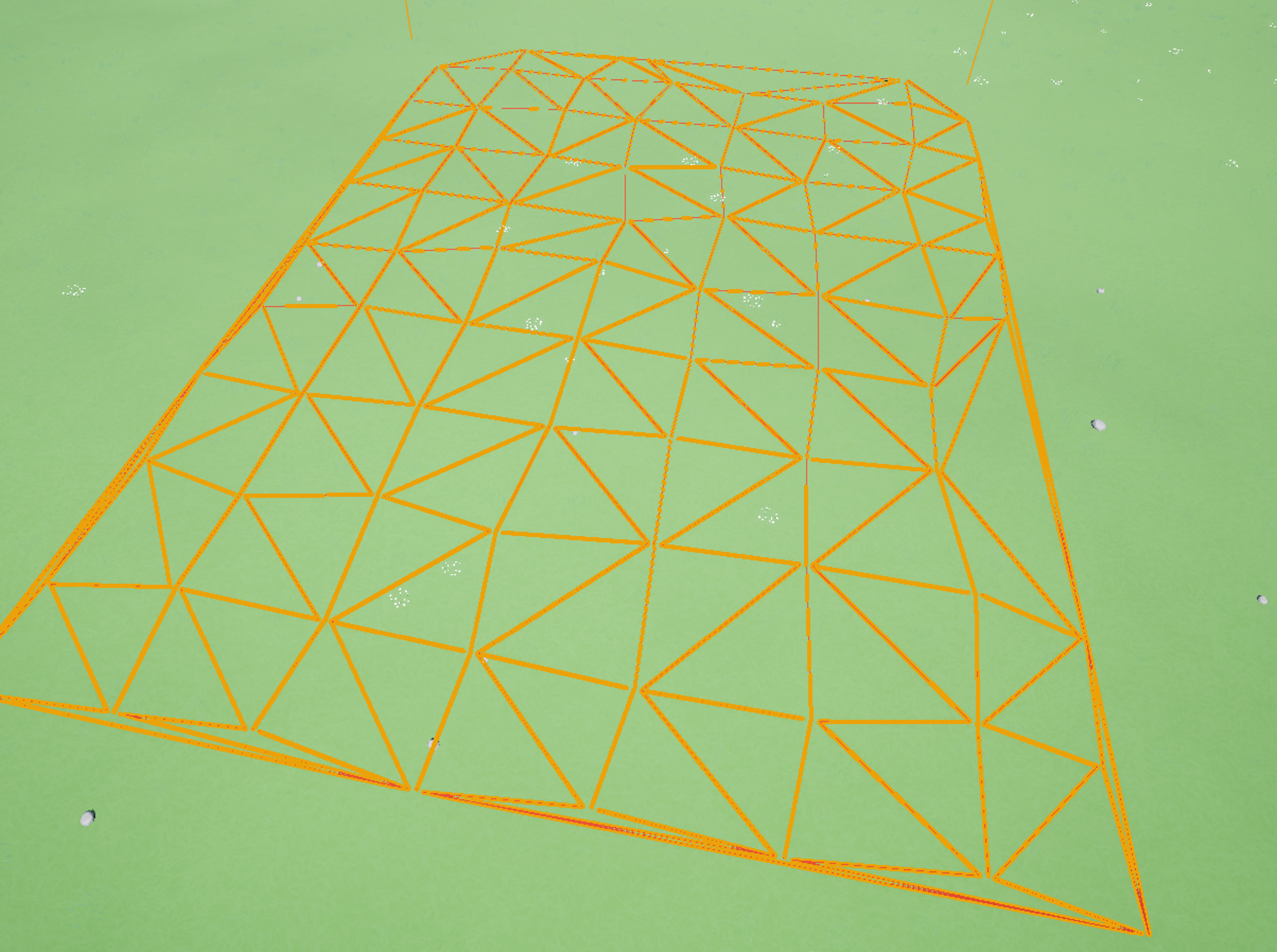
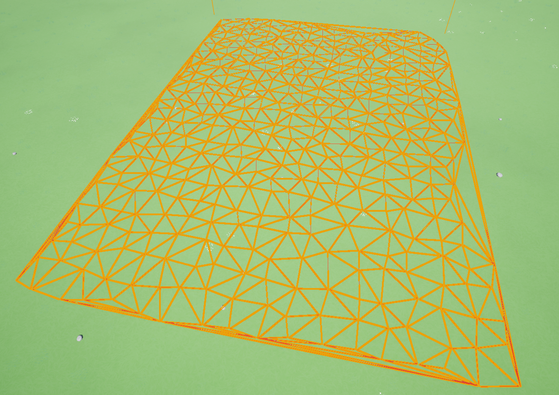
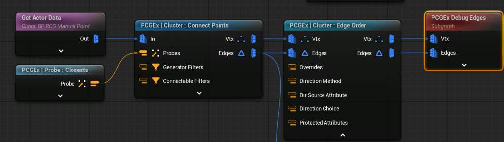
This gives something like this. Effectively getting landscape data, sampling the surface to get a set of datapoints (standard PCG). PCGEx Fuse handily merges points from that set based on distance. The below shows a difference – the image on the left has a tolerance of 4 times the one on the right, so more points are merged into one.
This is then fed through a Cluster Diagram node, in this case Delaunay 2D, which creates a nice graph between points. Finally, there is a PCGEx Debug node which will draw the edges of the graph for you.
A basic street
Thinking through what I want to achieve next, I was keep to understand how to build a main street/side streets. The PCGEx example project has an example map that looks roughly what I would want to achieve, but it’s fairly hard to track through exactly how it’s doing it, without basic understanding of some of the steps. Therefore I wanted to build up from scratch.
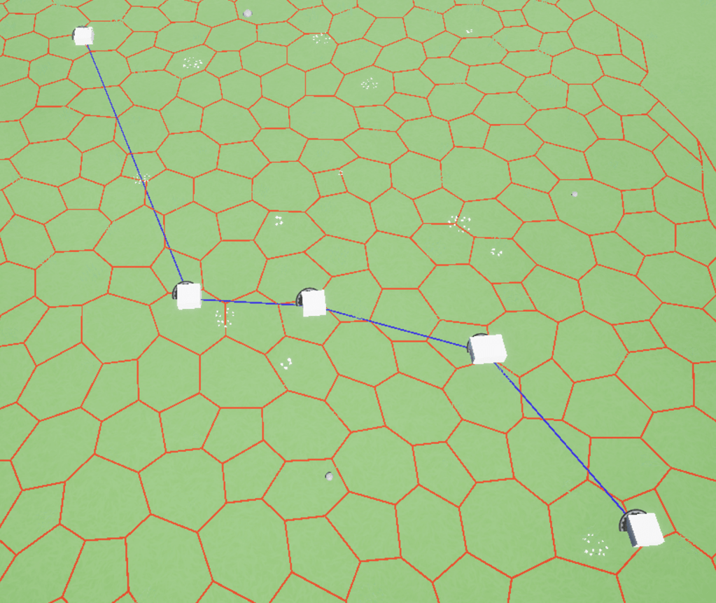
To start with, I create a very basic Actor Blueprint. A basic cube, plus a couple of variables. (that I don’t use yet). My thinking is that these could be used as intersection to put it in the spine of a main street. I dropped a few of them on the map. I then set about seeing how I could use these in a PCG graph.
This graph gets Actor Data (specifically of the class I just created). It then connects these points using a PCGEx node. Note the Probe bottom left – this was something I had to get my head around in PCGEx – things like filters or criteria have their own nodes where you set properties, and pass them into the node for use. I found it a bit weird (particularly later on, as you can see attributes it feels like the Probe doesn’t know about) but starting to get my head round it. This gave me something like the below.
Now for something that is probably comically ineffecient. I want to create side streets. I’m think to try it, I create a copy of a number of points along main street, then join them up.
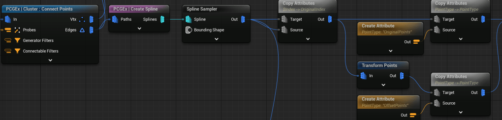
From the connect points in the previous step, I’ve got a number of vertices and edges. From that I use a PCGEx Create Spline node. Then I use a standard spline sampler – using the properties to split it into 24 “pieces”. After the spline sampler, I need to work towards 2 sets of points – I use the Copy Attributes node to add some data to each data set – the first node basically adds an Original Index attribute (so I know which ones to hook up later). I then transform the points (very basic add offset on y axis – I spent time on working on a good vector and got nowhere, so will come back to it), and the final copy attribute nodes in each stream denotes whether it’s an Original point or an offset point.
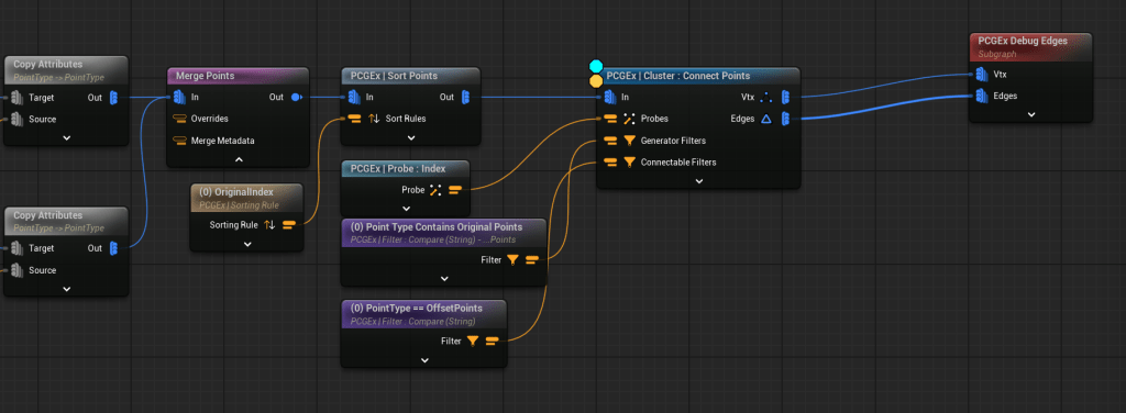
From each of the copy attribues, I’ve got a set of 24 points. I use the Merge node to put them in the same stream, then use Sort Points to Order them by Original index. This puts the points to be connected “beside” each other.
The Connect Points node then has to join the points together. I spend a lot of time on this, and not sure it was the best way. Basically there are 2 filters – a Generator filter, and a Connectable filter. I set these filters in the Comparison nodes – one for Original, and one for Offset points, so an original can’t connect to another original. The Probe – Index node is passed in, and this is my failing here, that tells the connect node to use an Offset of 1 – because I sorted the data, connection nodes should be 1 index away, and it’ll hook them up. I should have been able to use Original Index as the Attribute, but I simply couldn’t get this working. My approach works, but feels brittle.
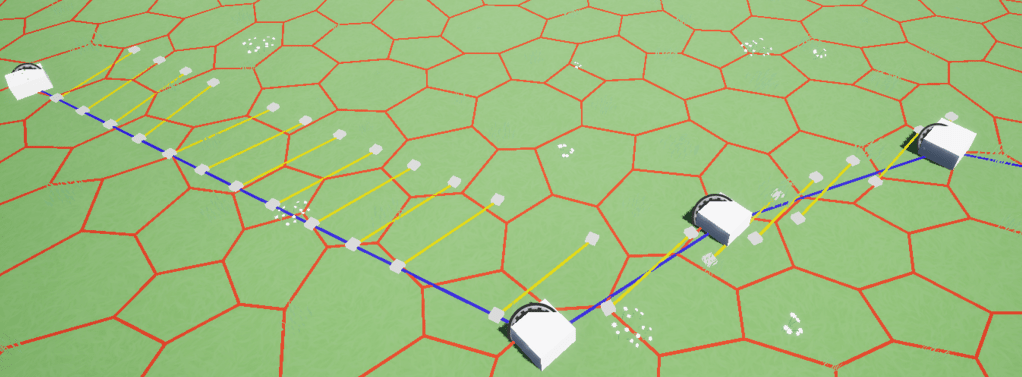
This is the output. Ideally I’d want the street points to be a consistent angle from the spline, but I spent a fair bit of time getting inconsistent vector/tangent results, so just got the flow above working. Next step is trying to get a bit more control on the angle.

Leave a comment